PIDE (PID Enhanced) is an advanced PID controller function block in Rockwell Automation’s Studio 5000 Logix Designer, used for closed-loop control with auto/manual, cascade, ratio, and feedforward capabilities.
2. Adding PIDE to a Project
- Open Studio 5000 Logix Designer.
- Navigate to Controller Organizer → Right-click on Program Routines → Select New Routine.
- Create a new Function Block Diagram (FBD) Routine.
- Drag & drop a PIDE instruction from the instruction toolbar.
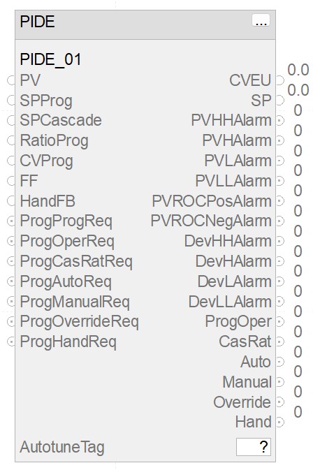
- Assign a Tag Name for the PIDE block (e.g.,
PIDE_01). - Link the inputs/outputs as needed.
3. Key PIDE Parameters
Process Variables
- PV (Process Variable): Actual process measurement.
- SP (Setpoint): Desired target value.
- CVEU (Control Variable): Controller output in engineering units.
Control Mode Selection
- ProgOper: Operator mode selection (1 = Auto, 0 = Manual).
- ProgManualReq: Forces the PIDE into manual mode.
- ProgAutoReq: Forces the PIDE into auto mode.
Tuning Parameters
- Kp (Proportional Gain): Increases/decreases responsiveness.
- Ki (Integral Gain): Corrects steady-state error.
- Kd (Derivative Gain): Counteracts rapid PV changes.
- Ts (Sample Time): Determines execution frequency of the PID loop.
- Bias: Default output value when no error exists.
Alarms & Limits
- PVHAlarm, PVLAlarm: High/low PV alarms.
- DevHAlarm, DevLAlarm: Deviation alarms.
- PVROCPosAlarm, PVROCNegAlarm: Rate-of-change alarms.
- SPHighLimit, SPLowLimit: Defines allowable SP range.
- CVHighLimit, CVLowLimit: Restricts output range.
| Parameter | Description | Importance | Typical Use Case |
|---|---|---|---|
| PV (Process Variable) | Real-time measured value of the process | Essential for feedback control | Used in feedback control loops for temperature, pressure, flow, or level control |
| SP (Setpoint) | Desired target value for the process | Defines process objective | Operators set SP for process control (e.g., maintaining tank level at 50%) |
| CVEU (Control Variable) | Controller output in engineering units | Drives the final control element | Determines actuator position in valves, motors, or pumps based on control logic |
| ProgAutoReq | Forces the controller into Auto mode | Required for automatic operation | Required for automatic process control (e.g., adjusting boiler temperature automatically) |
| ProgManualReq | Forces the controller into Manual mode | Allows manual operator control | Used when manual intervention is needed (e.g., maintenance mode or manual valve control) |
| Kp (Proportional Gain) | Determines system responsiveness | Key tuning parameter | Increasing Kp makes the system respond faster but may cause oscillations |
| Ki (Integral Gain) | Eliminates steady-state error | Prevents offset in control | Ki is used to eliminate long-term offset errors in temperature or pressure loops |
| Kd (Derivative Gain) | Reduces overshoot and oscillations | Enhances stability | Kd helps reduce overshoot in fast-changing processes like flow control |
| Bias | Default output value in Manual mode | Ensures smooth transitions | Used to ensure smooth transitions when switching between modes |
| PVHAlarm / PVLAlarm | High/Low PV alarm settings | Prevents unsafe process conditions | Triggers alarms when a process variable exceeds safe operational limits |
| SPHighLimit / SPLowLimit | Setpoint range constraints | Avoids unrealistic setpoints | Prevents operators from setting SP beyond physically safe values |
| CVHighLimit / CVLowLimit | Control output constraints | Protects actuators from overdriving | Limits CV to protect actuators from excessive load (e.g., preventing pump overrun) |
| PVROCPosAlarm / PVROCNegAlarm | Rate of change alarms | Detects sudden process deviations | Detects sudden process changes like rapid temperature drops in furnaces |
| DevHAlarm / DevLAlarm | Deviation alarms (SP vs PV) | Alerts when PV deviates too much | Warns operators when PV drifts too far from SP, ensuring stable control |
| Ts (Sample Time) | Execution time for the PIDE loop | Affects control loop responsiveness | Optimized for fast or slow processes (e.g., chemical vs. mechanical control loops) |
| FFGain (Feedforward Gain) | Compensates for measured disturbances | Improves control performance | Used to compensate for predictable disturbances in feedforward control strategies |
| Derivative Filter | Reduces noise in derivative action | Prevents excessive sensitivity | Reduces measurement noise impact when using derivative action in PID tuning |
| Override Mode | Allows safety interlocks to take priority | Ensures fail-safe operation | Ensures safe shutdown or process hold in emergencies (e.g., high-pressure trip) |
| AutotuneTag | Triggers automatic tuning of PIDE | Useful for optimal tuning | Auto-tunes PID settings to optimize control performance without manual tuning |
| Adaptive Gain Scheduling | Adjusts tuning dynamically | Improves performance for nonlinear processes | Adjusts PID parameters dynamically for nonlinear processes like batch reactions |
4. Modes of Operation
| Mode | Description |
|---|---|
| Auto | Adjusts CV automatically based on SP and PV. |
| Manual | Operator manually adjusts CV. |
| Cascade | PIDE gets SP from another loop (e.g., master loop). |
| Ratio | Control follows a ratio of another PV. |
| Override | Used for interlocks and safety constraints. |
| Hand | External control (e.g., from HMI/SCADA). |
5. Tuning Best Practices
1. Manual Tuning Approach
- Set Ki and Kd to 0, adjust Kp until oscillations are noticeable.
- Introduce Ki slowly to eliminate steady-state error.
- Adjust Kd to minimize overshoot and dampen oscillations.
- Fine-tune for best performance.
2. Auto-Tune Feature
- Use
AutotuneTagto let the controller determine optimal tuning values. - Ensure the process is at steady-state before starting auto-tuning.
3. Ziegler-Nichols Tuning Method
- Increase Kp until sustained oscillations occur.
- Record the Ultimate Gain (Ku) and Oscillation Period (Pu).
- Apply appropriate Ziegler-Nichols tuning formulas:
| Control Type | Kp | Ti (Ki) | Td (Kd) |
| P Control | 0.50 * Ku | N/A | N/A |
| PI Control | 0.45 * Ku | 0.85 * Pu | N/A |
| PID Control | 0.60 * Ku | 0.50 * Pu | 0.125 * Pu |
6. Commissioning Steps
- Verify PV and SP scaling to ensure correct engineering units.
- Check input/output connections and confirm correct wiring.
- Set appropriate limits for SP, CV, and PV.
- Monitor CV response and tune parameters as needed.
- Validate alarms to prevent unnecessary trips.
- Simulate worst-case conditions to ensure stability.
7. Troubleshooting & Maintenance
| Issue | Possible Causes | Solution |
| Overshooting SP | Kp too high | Reduce Kp |
| Slow response | Ki too low | Increase Ki |
| Oscillations | Kd too high | Reduce Kd |
| No CV output | CV limits too restrictive | Adjust CVHigh/Low Limits |
| Auto mode not working | SP or PV input issue | Check input scaling |
8. Advanced Features
Adaptive Gain Scheduling
- Adjusts PID parameters dynamically based on operating conditions.
- Useful for non-linear processes.
Feedforward Control
- Improves control response by compensating for known disturbances.
- Set
FFGainappropriately based on disturbance magnitude.
Derivative Filtering
- Reduces noise amplification caused by derivative action.
- Adjust
KdFilteras needed.
Data Logging & Trending
- Log PV, SP, and CV for performance analysis.
- Use FactoryTalk View SE/ME for real-time monitoring.
9. Key Studio 5000 Logix Designer Shortcuts
| Action | Shortcut |
| Open Tag Database | Ctrl + T |
| Force a Value | Right-click → Force |
| Search Tags | Ctrl + F |
| Go Online | Ctrl + Shift + O |
| Download to PLC | Ctrl + D |
10. Recommended Learning Resources
- Rockwell Automation Knowledgebase – www.rockwellautomation.com
- Studio 5000 Logix Designer Online Help (
F1in software) - PID Loop Tuning Books (e.g., “PID Control: Ziegler-Nichols and Beyond”)
Final Tip: PRACTICE & TEST YOUR LOOPS!
The best way to master PIDE is through hands-on experience. Simulate, tune, and analyze trends before applying to live systems.
🚀 Happy Automating! 🚀 by yourself or engage our services.